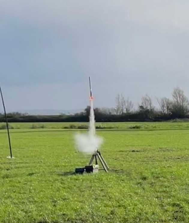
(1) Predicting the maximum height () and the maximum velocity () that a model rocket will achieve when launched. Also useful to know the time after launch of maximum altitude (). Three models. Excluding drag for simplicity.
FRAMING
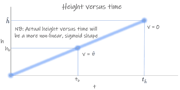
(2) At launch, time , the rocket's height and its velocity . After launch the rocket will accelerate until the motor burns out at . At , the rocket will be at height and velocity . The rocket will continue to rise upwards for distance , slowing because of gravity, until again. Then the rocket will be at , and the time will be .
(3) Relevant initial data that we can use to derive (, ), , are as follows:
- , the engine's burn time (NB: )
- , the engine's total impulse
- , the rocket's mass
- , acceleration down due to Earth's gravity
MODEL 1: NO DRAG, CONSTANT IMPULSE, VERTICAL FLIGHT, CONSTANT MASS
(4) The first model is simplest. It assumes no drag and that is constant over (all models in this note make this assumption). Model 1 also assumes no weathercocking and that rocket mass is unchanging. The results are the least accurate but it is a start.
(5) We can calculate by looking at the rate of acceleration during the boost phase, where is the acceleration provided by the motor and is the deceleration provided by gravity:
(6) Assuming constant impulse and no drag (3), the rocket will accelerate linearly from 0 to and the average velocity . Therefore to calculate :
(7) During the coast phase (NB: still assuming no drag), the rocket will linearly decelerate from to 0 due to gravity. Therefore, to derive we can calculate the duration of the coast phase and use (and ).
(8) In summary, the no-drag, constant impulse, vertical flight, constant mass model is as follows:
MODEL 2: NO DRAG, CONSTANT IMPULSE, WEATHERCOCKING, CONSTANT MASS
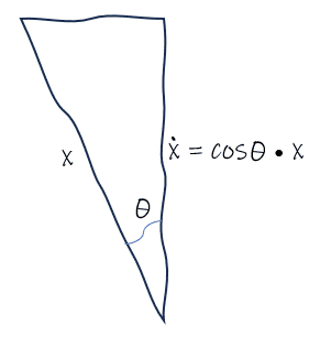
(9) If the rocket's launch is not perfectly vertical then some proportion of its acceleration is sideways, not vertical. This reduces the maximum vertical velocity and so also affects and . This can be seen in the following diagram where denotes the vertical component of an that is not wholly vertical.
(10) If the rocket weathercocks at angle then is as follows. Apart from using in place of , the calculations for and are unchanged from model 1, (8).
MODEL 3: NO DRAG, CONSTANT IMPULSE, WEATHERCOCKING, CHANGING MASS
(11) Although a model rocket's propellant mass is a small proportion of its weight (especially compared to the proportion propellant mass of full scale rockets), factoring it into the model can help improve its accuracy further.
(12) The rocket's mass is the body and propellant, . Assuming constant (3), it is reasonable to also assume that the propellant is burnt linearly.
(13) Therefore, the rocket's mass varies from to over the course of the burn phase, with average , whereas the rocket's mass is only for the entirety of the coast phase. The change in mass during boost affects . In turn this flows through into and therefore and .
(13) As a result, the modified equation for is as follows. All other equations are as in model 1, (8).
(15) Note that drag varies with mass and the rate of deceleration due to drag is proportionally greater when the rocker is lighter due to the reduced momentum. This affects the calculation of and also further directly affects . Modelling of drag is not considered in this note.
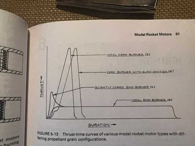
(16) Note that the impulse may vary during the burn; a typical impulse profile is shown below. Modelling variation in impulse over the course of a rocket motor's burn is outside of scope. The impact of this factor is highly dependent on the specific impulse profile. It is difficult to empirically determine an impulse profile and it is not clear what is an appropriate conceptual model. Therefore, in true engineering fashion, this consideration is disregarded.
 Handbook of Model Rocketry, G. Harry Stine
SUMMARY
(17) The formula for model 3 (no drag, constant impulse, weathercocking, changing mass) for the quantities that we care about in terms of the relevant initial data are:


